Chapter 5
Installation Manual
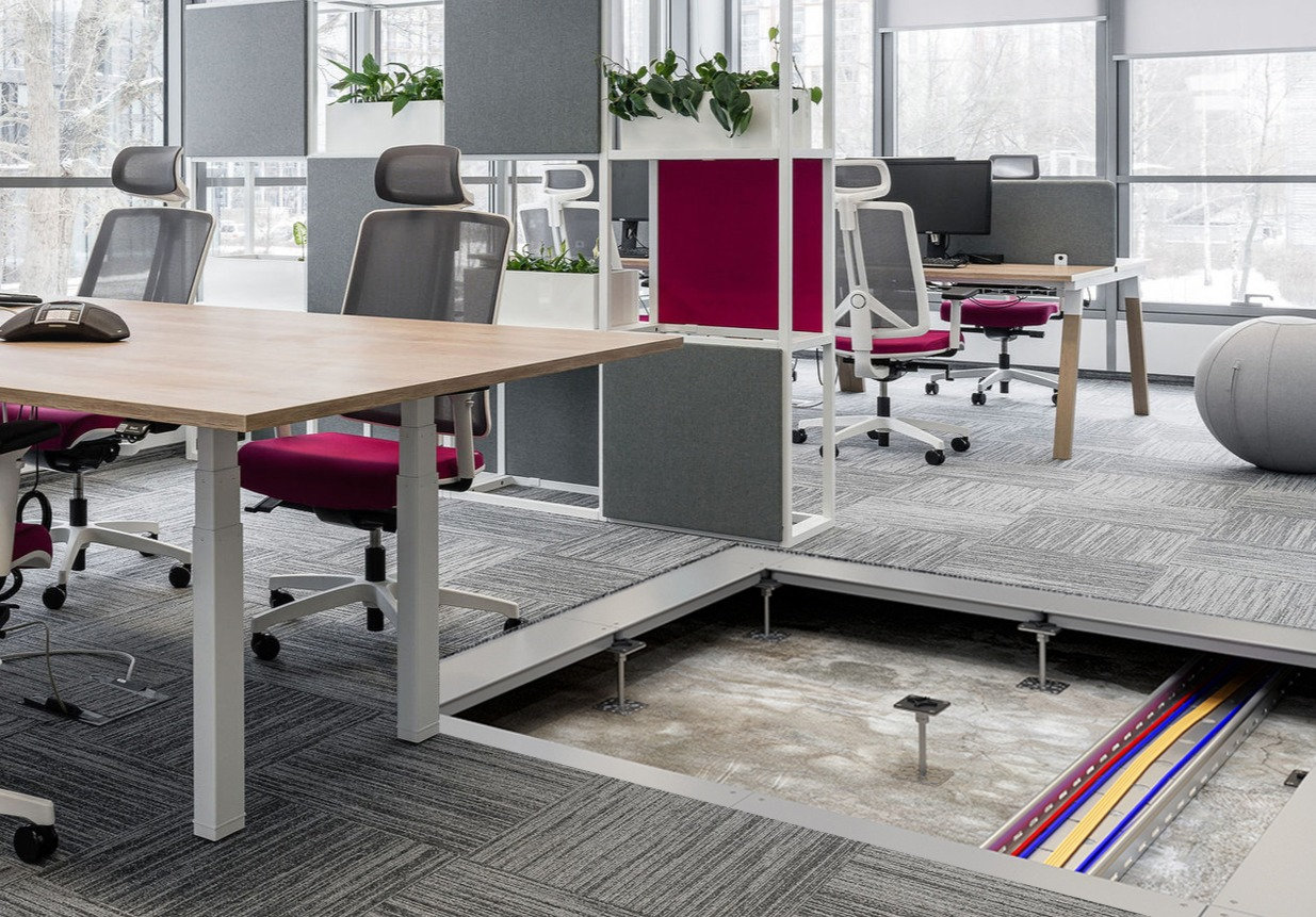
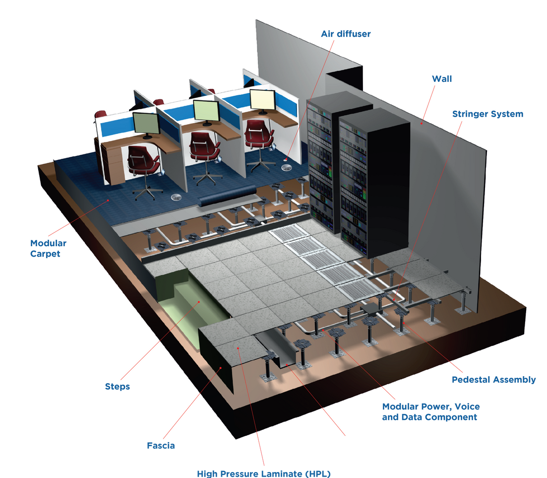
The following pages will help you with installing Unitile raised access floor products in office and equipment room applications. To help you navigate each section easily, we have provided a suitable illustration by highlighting the relevant areas. You can use links on the content page to refer to a particular section.
Job Site Preparation
A comprehensive understanding and control of the building space receiving the raised access floor are essential at the time of raised access floor installation.
The General Contractor and/or the Owner must be fully aware of your requirements. This includes the following:
Consent on means of access to the area
elevator, stairs, street level, loading dock, etc.
Storage conditions
Before commencing installation, a dry, secure storage space must be made available for the access floor materials.
Power available during installation (min. requirement 110- volt to 220- volts supply).
Drawings showing the size and configuration of the access floor area.
Identification of materials movement paths within the building
Plan the path along which your material would be moved from the trucks to the raised access floor installation area. A free path from an elevator and/or hoists to the area receiving the raised access floor material should be available.
Planning other jobs
Preferably, all overhead work should be completed before the installation. If overhead work is carried out after installation and the access floor is used as a work platform, ensure it's adequately protected, so there's no severe damage. This can be done by placing 19 mm thick sheets of plywood on the raised access floor.
Authenticate that the work conforms to the contract GFC (Goods For Construction) drawings and that both sides agree to the starting point before commencing work.
Installation Conditions
The installation area must be closed to the conditions with readings at 10 C to 32 C and 20% - 80% relative humidity, 24 hours a day and after installation
Identify the type and location of all equipment and services on fabricated stands (e.g. air handlers, power distribution units, etc.) Verify whether the equipment will be installed before or after the raised access floor.
The installation area should be free of other trades and materials and have adequate lighting and power.
The subfloor surface must be free of moisture, dirt, grease, oil and other substances.
The subfloor's condition should be checked to see if it is broken or dug out. The General Contractor should float a skim coat of cement over areas that show these conditions.
Subfloors other than concrete
You need to exercise extra care in the case of wood subfloors, vibration isolation pads, or concrete floors with existing floor coverings. If there's no alternative to installing the raised access floor over one of these subfloors, please conduct overturning moment tests to ensure that the pedestals adhered to them will meet the overturning moment specification.
Uneven Subfloors
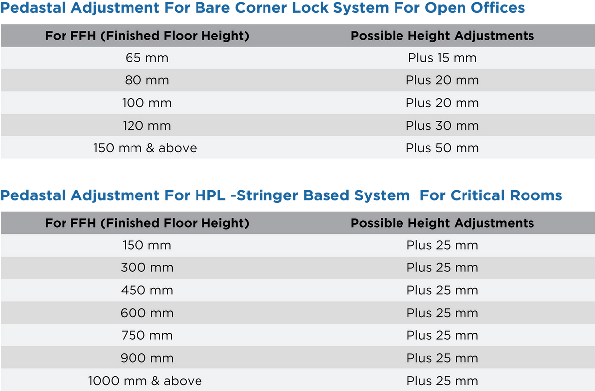
A laser must be employed to check the possibility of even subflooring before the installation. In locations with low areas in the subfloor, more than the height adjustment range of the pedestals may be needed. The adjustment ranges of pedestals and the corresponding head-to-base engagement requirements are shown below.
Slight condition
Use pedestal adhesive to compensate for a slight subfloor irregularity under the base plate. If the subfloor is very rough, apply additional adhesive.
Moderate Condition
To commence work, use a pedestal and a metal shim to compensate for a moderate irregularity under the base plate.
You need to exercise extra care in the case of wood subfloors, vibration isolation pads, or concrete floors with existing floor coverings. If there's no alternative to installing the raised access floor over one of these subfloors, please conduct overturning moment tests to ensure that the pedestals adhered to them will meet the overturning moment specification.
Installation at Site
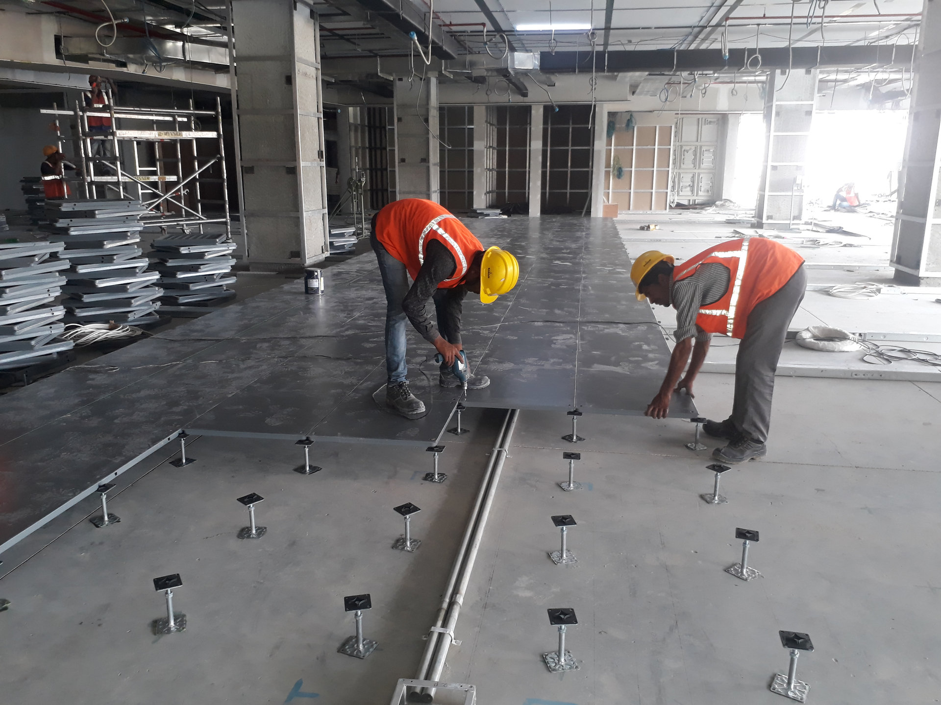
The installation of the raised access floor initiates with the field area.
Specific steps that need to be followed are listed below in sequential order:
Step 1
Verify field dimensions vs Drawings & check the subfloor for grade variations
Inspect the room dimensions with approved drawings and set up the laser to ensure the subfloor conforms to specifications.
Establish the exact, finished floor height by locating the benchmark set by the General Contractor.
Understand that the pedestals have limited adjustment ranges and the minimum stud-to-tube engagements must be maintained.
Confirm that the necessary pedestals are of the necessary height if the planned raised access floor elevation needs to be changed to meet the bottom of the door buck or some other fixed structure.
Step 2
Check starting point
Usually, the Architect, Engineer, or General Contractor work it out. If you find that by using the chosen starting point, the following conditions exist, you can seek permission to move the starting point:
Panels cut at the perimeter will be 125 mm wide or less, requiring supplemental support.
You will hit objects on the subfloor that could be circumvented.
The planned starting walls are cooked or not square-shaped.
Step 3
Establish control lines from starting point
Establishing the starting point and use of chalk, tape measure, laser and electronic transit are important to install the access floor.
Measure the accuracy of the control lines to ensure they are all located within 600mm of the wall.
Quality control is essential to ensure the accuracy and reliability of the installation.
Use the appropriate tools and methods to measure and draw the control lines accurately and check the distance of each line to the wall is less than 600mm.
Step 4
Spread pedestals
Starting at 3600 mm, draw chalk lines perpendicular to each control line and mark the intersection points in the grid as the pedestal shot points. To accurately set the pedestal elevations, use a laser or transit at the shot points. Utilize the 3600 mm levelling bar to adjust the height of all other pedestals accordingly. Lastly, place all pedestals in their approximate spots, with only the shot point pedestals requiring precision in their placement.
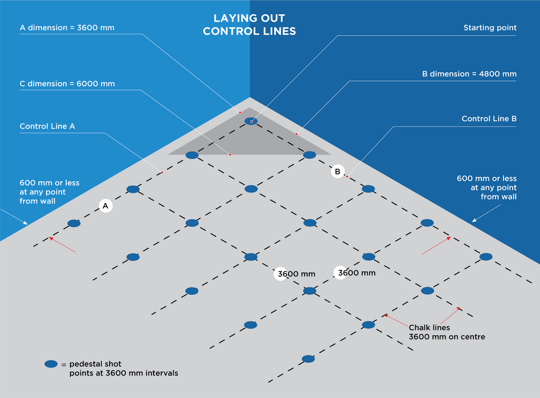
Dimension table:
To verify perpendicularity when laying out control lines with a tape measure

Step 5
Level pedestals in the proper position
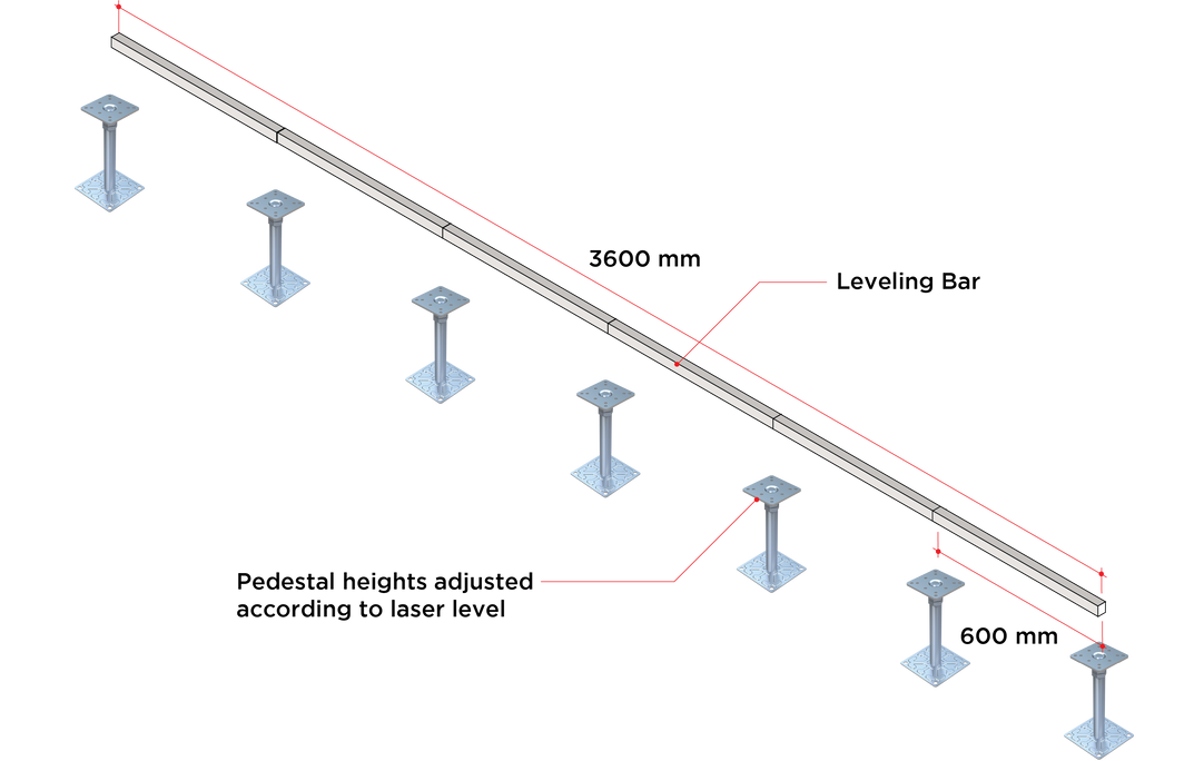
Using a laser, shoot in a pedestal assembly to the proper elevation at each chalk line intersection. Once the pedestals at the intersection are adjusted, a 3600 mm levelling bar made of extruded aluminium with 38 mm x 75 mm, straight (without a bow in any direction) must be used to precisely position and set the height of the remaining pedestals. The levelling bar must be marked every 600 mm. To set the height of the remaining pedestals, the bar must be positioned to cover the pedestals that were adjusted by the laser and then adjusted to 60 mm intervals, so that they meet the bottom of the bar.
To ensure a level access floor with no rocking panels, all pedestal heads must be firmly pressed against the bottom of the bar before raising it. The finished access floor should be level within 1.5 mm in 3600 mm of length and 3 mm of overall span. To achieve this, first two parallel rows of seven pedestals 3600 mm apart should be established. Then, turn the bar 90 degrees and use it to position and set the pedestals between the two rows until a 3600 mm by 3600 mm section with pedestals on 600 mm centers is obtained. This process must be repeated for each 3600 mm by 3600 mm section.
Step 6
Attach pedestals to the subfloor with adhesive
Using a spatula, one should carefully apply adhesive to the bottom of each levelled pedestal base and tilt it without changing its location. Then, the excess adhesive should be scraped off with the spatula, ensuring it ooze from at least three sides for full coverage.
For Corner Lock/ESRG systems up to 300 mm FFH, pedestals should be mounted to the subfloor using adhesive only, while for pedestals above 300 mm FFH, adhesive and two wood screws in diagonally opposite directions should be used. Finally, users should allow 60 minutes of adjustment time before the adhesive sets.
To ensure a successful floor installation, it is essential to properly mount the pedestals to the subfloor. For Corner Lock/ESRG systems up to 300 mm FFH, use adhesive, and for systems above 300 mm FFH, use adhesive and two wood screws in the diagonally opposite direction. Once the pedestals are placed, you have roughly 60 minutes before the adhesive begins to set, allowing you to make final adjustments.
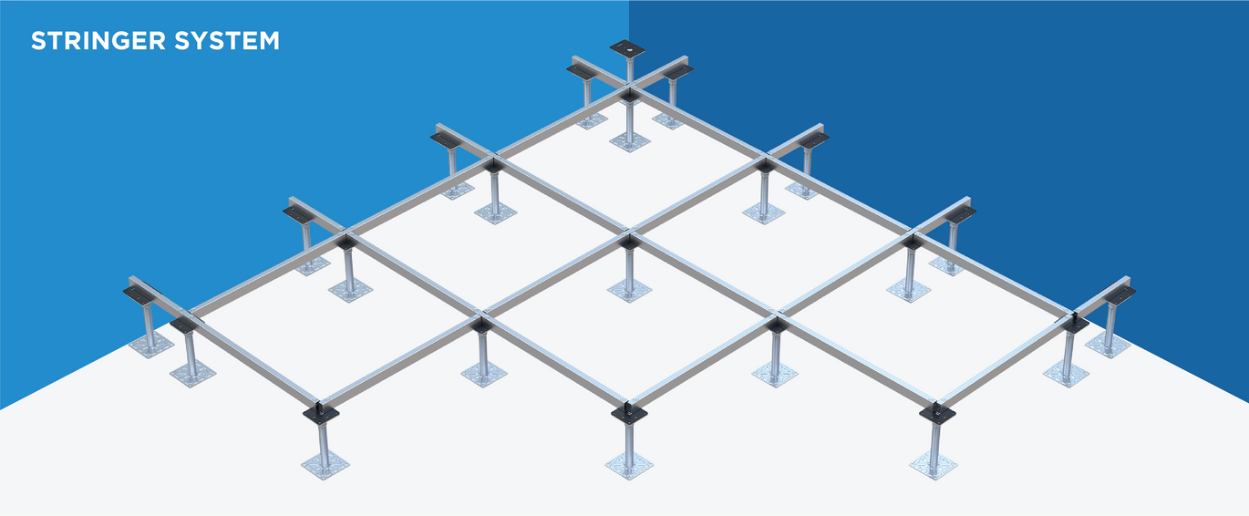
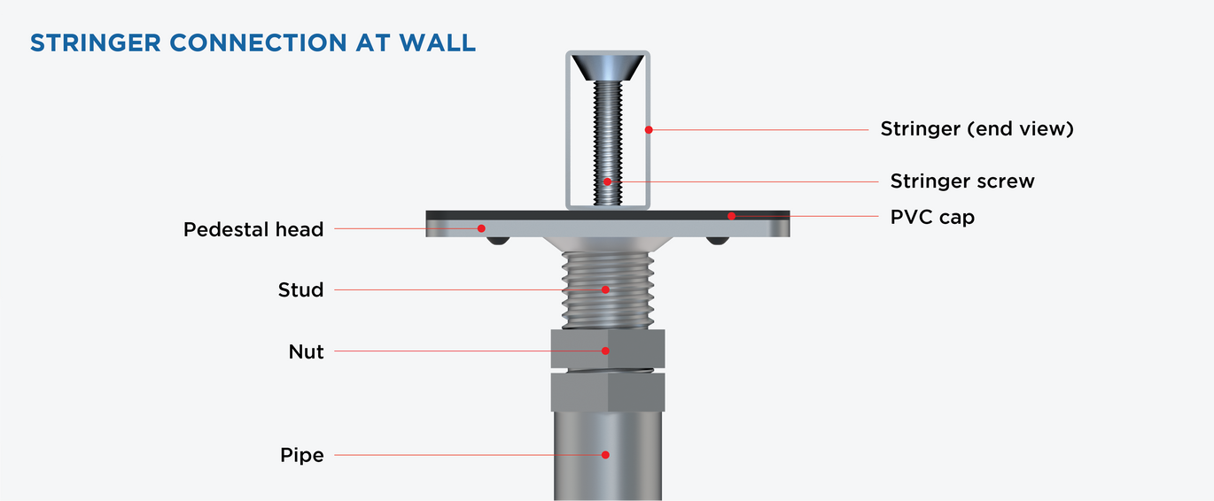
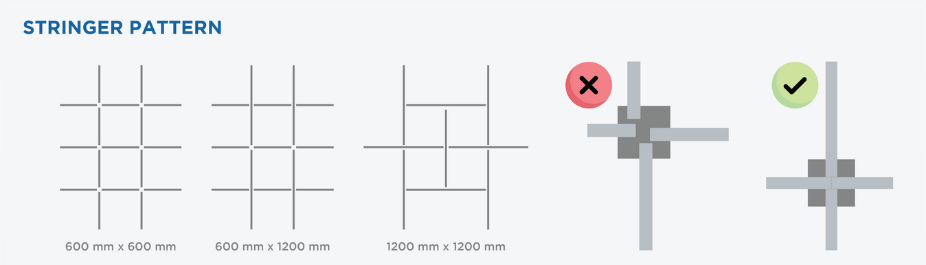
For stringer systems, use a torque-limiting screw gun to secure the stringers to the pedestal heads, setting the torque to 30-inch pounds - neither over-tightening nor under-torquing the screws, as it can affect the electrical continuity of the floor system.
For Unitile bare corner lock system: If the Unitile bare corner lock system is utilized, lock the panels to understructure as you proceed. Use a torque-limiting screw gun and set the torque to 30-inch pounds, ensuring no over-tightening.
Step 7
Create the L section (Stringer system)
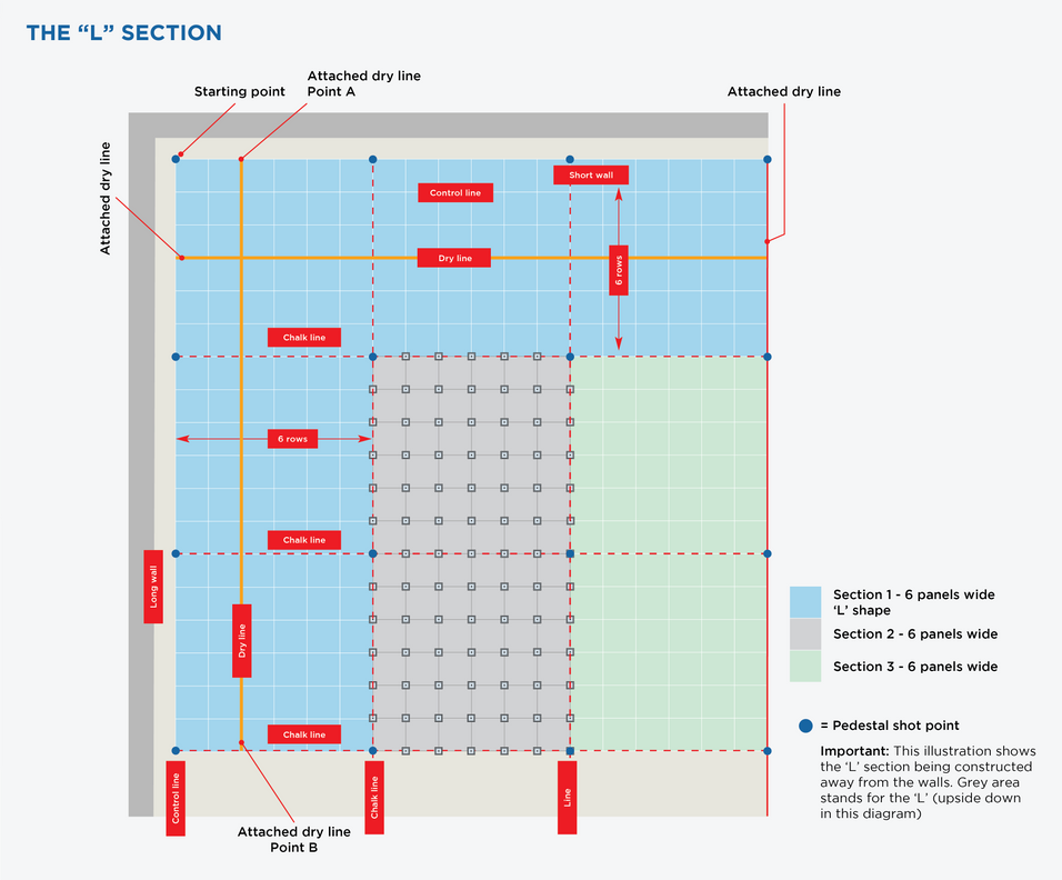
It's essential to begin installation with an L-shaped stringer system. This system acts like a giant carpenter's square, providing a straight edge for the remaining panels to fit against.
Instructions for Creating the Long Leg of the L Section:
Start by laying in panels at the starting point. Ensure that the pedestals nearest the wall stay on the control lines.
Lay six rows of panels along the longer wall to create the length of the leg.
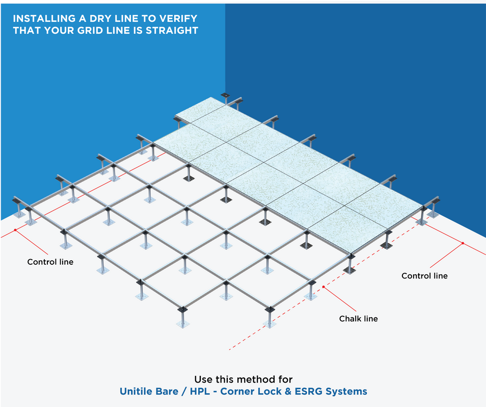
Once the leg is fully installed, use a dry line or a laser line to confirm that it is straight on the raised access floor.
How To Install A Dry Line
Secure a dry line to a pedestal at the wall near your starting point, and run it along the floor surface between two panels (as per the L Section diagram on page #17). Wrap the line over a spacer, pass the leg length, and attach it to the corresponding pedestal at the other end, making sure the line is fastened in the same way with a spacer at the top. Supervision must ensure that the seam between the second and third rows of panels is directly below the dry line.
Then, repeat this step in the other direction to create the other leg of the L section.